-40%
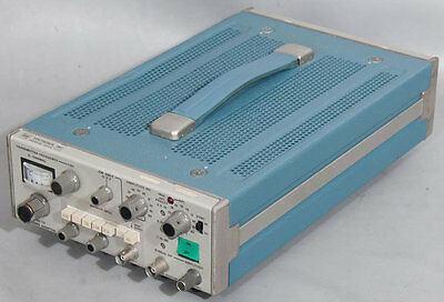
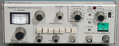
Tektronix 1405 NTSC Television TV Sideband Adapter
$ 527.99
- Description
- Size Guide
Description
Tektronix 1405 NTSC Television TV Sideband AdapterComes with a manual and what you see in the pictures. If you don't see it, you probably wont get it.
Specifications are from Tektronix and may vary slightly due to upgrades, options, or revisions this unit may or may not have.
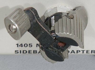
This unit is sold fully tested and guaranteed to work for 30-days, parts and labor, excluding freight. Please note the broken plastic on the Transmitter Frequency Knob.
Description:
The 1405 NTSC Television Sideband Adapter is an accessory instrument which is used with a spectrum analyzer, such as the 7L12 or 7L13, to analyze the video output of a television transmitter. The 1405 generates a composite video signal, the "picture" portion of which is a constant-amplitude sinusoidal signal that sweeps continuously and periodically between 0 and 15 MHz. This signal is applied as modulation to a television transmitter. The transmitter output is displayed on the spectrum analyzer, and appears as the transmitter's response curve. The 1405/spectrum analyzer combination will display the frequency response characteristics of RF and IF circuits for transmitters with carrier frequencies up to 1 GHz. Video circuits (zero frequency offset) can also be analyzed.
The swept portion of the 1405 output signal is produced by mixing the 1405 local oscillator with the 7L12 or 7L13 first local oscillator. The first local oscillator produces a sweeping signal whose frequency limit depends upon the input frequency (tuned to the transmitter frequency), and the FREQ SPAN/DIV setting of the spectrum analyzer. Sync and blanking signals are combined with the sweep to form the composite output signal. The internal sync signal can be switched off for sinusoidal sweep only, or when external blanking is used. External blanking allows either full-field or single-line operation, a feature useful for in-service testing.
The output amplitude of the cw portion of the composite video signal can be varied from 0 to 100 IRE in 10-IRE steps. The average picture level (APL) can also be varied from 0 to 100 in 10-IRE steps. Three adjustable, preset APLs are provided, and can be selected for rapid checks. If a combination of cw amplitude and APL exceeds tv transmitter modulation limits, internal logic will clamp the APL to 50 IRE and light an UNCAL indicator as a caution.
Five intensity marker frequencies related to tv transmission standards are provided; a sixth marker oscillator is available for a user-provided crystal. The intensity and width of the displayed markers are adjustable.
A television transmitter's aural fm deviation can be checked with the 1405, using the 10.396 kHz signal output. This signal, applied to a transmitter's aural input at the amplitude that produces the first carrier null, corresponds to ±25 kHz of frequency deviation, or 100% modulation.
Electrical Specifications:
Transmitter Frequency (Frequency Offset):
Range:
Will tune and provide a swept video output for a 7L12 or 7L13 center frequency range of 0 to 1 GHz.
FREQUENCY Dial Accuracy:
When properly tuned to transmitter frequency, dial reading is within 20 MHz.
Fine Tuning Range:
From ±0.5 MHz to ±1.25 MHz, depending upon transmitter frequency setting.
Tuned Frequency Drift:
Less than 1 MHz per hour after a 30-minute warmup.
Local Oscillator Input:
Requires +5 dBm to +10 dBm for a constant output level. THe frequency is 2095 MHz to 3095 MHz. (This level and frequency is provided by the 1st LO OUTPUT on the 7L12 above SN B160000 or with LO Output Mod, or the 7L13.)
Output Signal Level:
Amplitude (Sync Off):
100 IRE equals 0.714 V P-P when terminated in 75 Ω.
Output Impedance:
75 Ω ±1% at 100 IRE and ±2% from 0 to 90 IRE.
Step Variable:
0 to 100 IRE in 10-IRE steps.
Accuracy at 0 IRE Setting (Relative to 100 IRE):
0.1 MHz to 5 MHz, greater than 40 dB down; 5 MHz to 10 MHz, greater than 33 dB down; 10 MHz to 15 MHz, greater than 30 dB down.
CW Output Amplitude:
No change in relative level between cw and line rate blanking. Single-line cw amplitude within 0.2 dB of the cw level.
CW Only:
0.6 V to 1.3 V P-P when terminated in 75 Ω. Reference line on variable at about I V P-P.
Output Level During Blanking:
0 V ±0.01 V at 0 IRE; 0 V ±0.04 V at 100 IRE from 0 to 1 MHz; 0 V ±0.02 V at 100 IRE above 1 MHz.
CW Output Harmonics:
2nd harmonic content dependent upon spectrum analyzer 1st LO OUTPUT. 3rd harmonic content down 40 dB from 0.1 MHz to 5 MHz; down 35 dB from 5 MHz to 10 MHz.
Video Monitor:
Same as Output Signal Level within 5%.
Flatness:
1405:
Within ±0.1 dB from 100 kHz to 10 MHz; within ±0.2 dB from 10 MHz to 15 MHz; and within ±0.4 dB from 50 kHz to 20 MHz.
1405 plus 7L12 or 7L13:
TRANSMITTER FREQUENCY greater than 20 MHz: within ±0.2 dB from 100 kHz to 10 MHz, increasing to ±0.3 dB at 15 MHz. Within ±0.5 dB from 50 kHz to 20 MHz.
TRANSMITTER FREQUENCY 0 to 20 MHz:
Within ±0.5 dB from 100 kHz to 15 MHz.
System Span:
7L12:
Equal to or greater than 200 kHz per division.
7L13:
Equal to or greater than 100 kHz per division.
Video Frequency Range:
15-0-15 MHz, with 1405 TRANSMITTER FREQUENCY controls properly set.
Average Picture Level (APL) Variable:
0 to 100 IRE in 10-IRE steps.
Accuracy:
±2 IRE.
Three Preset Levels:
PRESET A, 0 to 50 IRE; PRESET B, 25 IRE to 75 IRE; PRESET C, 50 IRE to 100 IRE.
Horizontal Sync and Blanking Duration:
Within NTSC limits (no vertical interval is provided). Transition time is 0.24 µs ±10%, from 10% to 90% points.
External Blanking Modes:
A:
0 V turns cw on, greater than -5 V turns cw off. DC coupled (e.q., composition blanking).
B:
TTL pulse from > +2.5 V to 0 V turns cw on (e.q., 1480 line strobe). Minimum pulse length, 50 µs.
Marker and Z-Axis Output:
Marker Frequencies, NTSC Version:
0.75 MHz, 1.25 MHz, 3.58 MHz (color subcarrier), 4.18 MHz and 4.75 MHz.
Accuracy:
±0.01% of frequency selected (crystal controlled). Additional marker oscillator accepts user supplied crystals.
1
External Marker Input:
Accepts 0.2 MHz to 10 MHz, 1 V P-P nominal.
Internal Marker Output:
Marker crystal frequencies, nominal output level 0.75 V P-P or greater.
Notes:
Note 1:
Crystal Requirements: Maximum frequency 10 MHz, Series resonant, R
s
less than 1000 Ω, Q greater than 5000, case, HC-6/U or HC-25/U.
Z-Axis Output Amplitude:
Up to about +10 V and -3 V into 500 Ω. Minus voltage intensifies trace to provide markers (variable with INTEN control); dark zone identifies middle of marker. About +10 V (fixed) blanks trace during blanking internal.
Aural Output:
Output Frequency:
10.396 kHz, ±0.01% (crystal controlled).
CW Output Amplitude:
Variable up to at least +12 dBm into 600 Ω (about 10 V P-P). Harmonics down 45 dB or more.
Environmental Specifications:
Operating Temperature Range:
0°C to +50°C.
Non-operating Temperature Range: -40°C to +75°C.
Operating Altitude Range:
to 15,000 feet.
Non-operating Altitude Range:
to 50,000 feet.
For Domestic Customers: Packaging, handling, and order processing included in shipping in all domestic shipments as quoted by the shipping calculator. For International Customers there is a .00 minimum for packaging, handling, and order processing. International shipping to be determined by destination.
Prior to shipment I will need to know the following information (filled out on a form that I will send you) for International Customers or Packages/Freight being Forwarded internationally. International customers may also be subject to a freight forwarder form if applicable.:
(1) Are you the end-user of this item?
(2) If you are not the ultimate end-user of the item, please state the ultimate end user's name.
(3) What is the ultimate country destination?
09/03/13
